Tuesday, August 12, 2014

Dynamic Controls in LabVIEW at Runtime: Fun with LabVIEW

Adding controls to a LabVIEW VI front panel at runtime is a very intriguing idea. We began to explore this a couple years ago and found many rich resources online in blogs and discussion forums using which we were able to build a complete solution. So, first things first! We would like to give credit to a post from Jhambhekar Automation we used as our main approach for this fun project.

Problem: How can we add controls to a LabVIEW front panel at runtime?

Solution: Using the "Call Library Node" block in LabVIEW build a wrapper around the Window user32.dll to use function call for windows programming.

Demo Video:

Details:

There are several posts on LabVIEW forums including LAVA and NI discussions where a wrapper library for user32.dll can be downloaded. A post on how to call a DLL from LabVIEW can be found here.

1. Grab handle to Main VI window: The main idea here, is to use the user32 dll function "Find Window" and passing the FP title to get the handle to the VI front panel window. This handle should be used through your code as the parent handle. Figure 1 shows the use of this user32 function.
Figure1: Use FindWindow to grab parent VI handle
 2.  Programmatically launch second VI: Each control to be added to the main VI at run time is actually another VI. You may simply add a control to the front panel of a second VI, reduce the size of the front panel to fit the displayed control. Programmatically launch and run the VI with the control.
3. Set Main VI as Parent to new VI: Next, in the VI launched in step 2, use the same FindWindow function to grab its own handle and then use the "SetParent" user32 function to set the main VI as its parent. Figure 2 shows this,
Figure 2: Add second VI as child window to Main VI


This will add the new VI as an embedded window in the main VI.
4. Reshape VI from step 2: We made use of  the "getWindowRegion" to get the region of an irregular shape (device/control to be displayed in the second VI) and then passed it to the "setWindowRegion" user32 function to reshape the child window (in this case the devices) we want to add in the Main VI.
5. Use custom cursors: We also used cursor functions from the user 32 to add drag and drop effects. This can now be done using the cursor utilities that are available with the LabVIEW base package here.

Note: Step 4 is to be implemented in the "child" VI and step 5 is to be implemented in the Main VI.

Conclusion: We aim to demonstrate that the discussion forums can be a powerful resource for your LabVIEW applications. The project described here is a result of several ideas we came across online as well as some of our own. The other point we want to stress on is that programming in LabVIEW can be made more enjoyable that it already is!!!

Note: We tried our best to give credit to posts and blogs from where we gathered resources. Please excuse us if we missed out any.

-Wakefield Engineering Team


Friday, July 11, 2014

LabVIEW interface for USB devices (libusb .NET)


Recently, while testing USB communication with a device that used libusb drivers, we had a choice of using Java or C++ as a platform for developing the required test programs. Instead, we decided to spend some time on our preferred platform, LabVIEW from National Instruments.
Figure 1: EZ USB FX2LP used in ZTEX USB FPGA 1.15 board
The bindings table on the libusb wesite lists all the different languages that can use libusb drivers. Note that LabVIEW is not listed among them. There are several postings on the LabVIEW discussion groups that suggest creating wrapper dlls around the libusb dll and creating a VISA driver for the USB devices. Each of these approaches have their merits in application, performance, robustness and capabilities. The approach that is suggested in this write up and we used is a quick and simple method to get your communications tested. 
The development board shown in the picture is 
a development platform from Ztex with an on-board Spartan 6 FPGA and a Cypress FX2LP 8051 core microcontroller for USB connectivity. For the sake of testing the USB communication, the FX2LP is configured in Slave FIFO mode, with the FPGA acting as a master. The overall configuration of the FX2LP is as follows:

  • EP2, BULK, IN, 512, Quad Buffered
  • EP6, BULK, OUT, 512, Dual Buffered
  • Internal CLK, 30 Mhz, AUTOIN, WORLDWIDE
Question: How do we build a quick USB interface within LabVIEW for devices that use the libusb driver?

Solution: Use the DotNET Binding provided at the libusb website  or  here within the .NET container in LabVIEW.

Details:

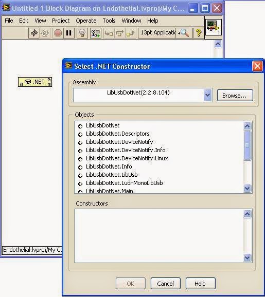
Figure 2: Adding the .NET constructor to a VI
  1. Download and install the LibUSBDotNET C# USB Library from any of the above links. 
  2. Drop a .NET constructor on the block diagram of a LabVIEW VI. Double click on the constructor and choose the libusbdotnet.dll from your installation folder
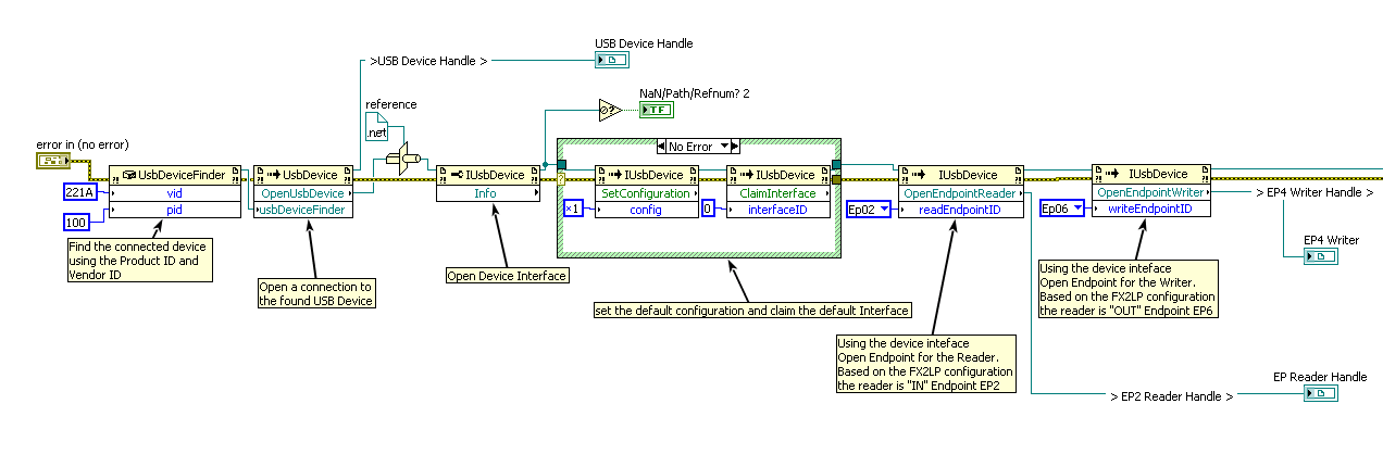
  3. The sequence for establishing a USB data connection to FX2LP using the .NET library is as follows:
    1. Find the device using the UsbDeviceFinder Constructor and the unique product ID and Vendor ID.
    2. Open a connection using the static function call "OpenUSB Device" in the UsbDevice Class 
    3. Select the default configuration and claim the default interface
    4. Use the reference wire from previous step to open and obtain a handle to a read endpoint (EP2)
    5. Use the reference wire from step 3 to open and obtain a handle to a write end point (EP6)
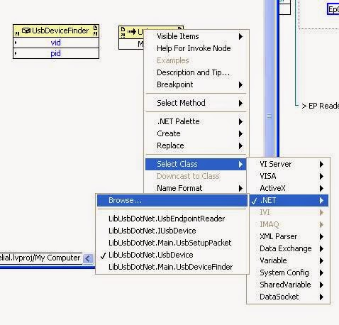
    6. Note: Steps 2 to 5 use static function calls in LabVIEW. Browsing through a .NET constructor node will not expose these methods for use. Instead, drop a "Invoke Method" block on your diagram, right-click and navigate to SlectCLass->.NET-> Browse. and choose LibUsbDotNet.IUsbDevice. (figure 3)

Figure 3: Calling a static function in LabVIEW
  • The following figure lays down the whole sequence of initiating a data connection to a USB device using a .NET binding for libusb drivers.

Figure 4: Sequence of execution to open read and write endpoints for a USB connection

  • The read endpoint is used to receive data from the USB device. The "IN" is always with respect to the host, which in this case is the computer running this LabVIEW VI. Similarly, the write endpoint is used to send data to the device. This is the "OUT" endpoint. This idea is depicted in the following figure

Figure 5: Write to and Read from USB Device
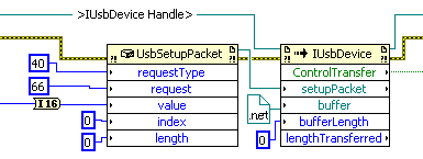
  • A command does not use the EP6 write endpoint. To send a vendor command to the device, use the IUsbDevice reference to invoke the ControlTransfer method. The UsbSetupPacket constructor has to be called first to generate the setupPacket to be sentout as shown in figure 6. Note that the control command request number (66 in this case) should be configured in the FX2LP. 


Figure 6: Sending a control command to USB device
  • Following the best practices of any software application development, do not forget to close the opened references before the program terminates. (See Figure 7)

Figure 7: Close USB Device references
The scientists and engineers at Wakefield Engineering hope this article helps you in optimizing the development time for your usblib devices